


Cisco VPN Client Configuration - Setup for IOS Router
Cisco VPN Client Configuration - Setup for IOS Router
|
Remote VPN access is an extremely popular service amongst Cisco routers and ASA Firewalls. The flexibility of having remote access to our corporate network and its resources literally from anywhere in the world, has proven extremely useful and in many cases irreplaceable. All that is required is fast Internet connection and your user credentials to log in – all the rest are taken care by your Cisco router or firewall appliance.
To initiate the connection, we use the Cisco VPN client, available for Windows operating systems (XP, Vista, Windows 7 - 32 & 64bit), Linux, Mac OS X10.4 & 10.5 and Solaris UltraSPARC (32 & 64bit), making it widely available for most users around the globe. Cisco VPN Clients are available for download from our Cisco Download section.
The Cisco VPN also introduces the concept of ‘Split Tunneling'. Split tunneling is a feature that allows a remote VPN client access the company's LAN, but at the same time surf the Internet. In this setup, only traffic destined to the company's LAN is sent through the VPN tunnel (encrypted) while all other traffic (Internet) is routed normally as it would if the user was not connected to the company VPN.
Some companies have a strict policy that does not allow the remote VPN client access the Internet while connected to the company network (split tunneling disabled) while others allow restricted access to the Internet via the VPN tunnel (rare)! In this case, all traffic is tunnelled through the VPN and there's usually a web proxy that will provide the remote client restricted Internet access.
From all the above, split tunneling is the most common configuration of Cisco VPN configuration today, however for educational purposes, we will be covering all methods.
Setting up a Cisco router to accept remote Cisco VPN clients is not an extremely difficult task. Following each step shown in this article will guarantee it will work flawlessly.
Below is a typical diagram of a company network providing VPN access to remote users in order to access the company's network resources.
The VPN established is an IPSec secure tunnel and all traffic is encrypted using the configured encryption algorithm:
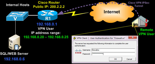
The Cisco IPSec VPN has two levels of protection as far as credentials concern. The remote client must have valid group authentication credential, followed by valid user credential.
The group credentials are entered once and stored in the VPN connection entry, however the user credentials are not stored and requested every time a connection is established:
We should note that configuring your router to support Point-to-Point Tunnel Protocol VPN (PPTP) is an alternative method and covered on our Cisco PPTP Router Configuration article, however PPTP VPN is an older, less secure and less flexible solution. We highly recommend using Cisco IPSec VPN only.
In order to configure Cisco IPSec VPN client support, the router must be running at least the 'Advanced Security' IOS otherwise most of the commands that follow will not be available at the CLI prompt!
To begin, we need to enable the router's 'aaa model' which stands for 'Authentication, Authorisation and Accounting'. AAA provides a method for identifying users who are logged in to a router and have access to servers or other resources.
AAA also identifies the level of access that has been granted to each user and monitors user activity to produce accounting information.
We enable the 'aaa new-model' service followed by X-Auth for user authentication and then group authentication (network vpn_group_ml_1):
R1# configure terminal
R1(config)# aaa new-model
R1(config)# aaa authentication login default local
R1(config)# aaa authentication login vpn_xauth_ml_1 local
R1(config)# aaa authentication login sslvpn local
R1(config)# aaa authorization network vpn_group_ml_1 local
R1(config)# aaa session-id common
R1(config)# aaa new-model
R1(config)# aaa authentication login default local
R1(config)# aaa authentication login vpn_xauth_ml_1 local
R1(config)# aaa authentication login sslvpn local
R1(config)# aaa authorization network vpn_group_ml_1 local
R1(config)# aaa session-id common
When trying to establish an IPSec tunnel, there are two main phase negotiations where the remote client negotiates the security policies and encryption method with the Cisco VPN router.
Now we create the user accounts that will be provided to our remote users. Each time they try to connect to our VPN, they will be required to enter this information:
R1(config)# username adminitrator secret $cisco$firewall
R1(config)# username firewallcx secret $fir3w@ll!
R1(config)# username firewallcx secret $fir3w@ll!
We next create an Internet Security Association and Key Management Protocol (ISAKMP) policy for Phase 1 negotiations. In this example, we've create two ISAKMP policies, and configure the encryption (encr), authentication method, hash algorithm and set the Diffie-Hellman group:
R1(config)# crypto isakmp policy 1
R1(config-isakmp)# encr 3des
R1(config-isakmp)# authentication pre-share
R1(config-isakmp)# group 2
R1(config-isakmp)#
R1(config-isakmp)#crypto isakmp policy 2
R1(config-isakmp)# encr 3des
R1(config-isakmp)# hash md5
R1(config-isakmp)# authentication pre-share
R1(config-isakmp)# group 2
R1(config-isakmp)# exit
R1(config-isakmp)# encr 3des
R1(config-isakmp)# authentication pre-share
R1(config-isakmp)# group 2
R1(config-isakmp)#
R1(config-isakmp)#crypto isakmp policy 2
R1(config-isakmp)# encr 3des
R1(config-isakmp)# hash md5
R1(config-isakmp)# authentication pre-share
R1(config-isakmp)# group 2
R1(config-isakmp)# exit
We now create a group and configure the DNS server and other parameters as required. These parameters are passed down to the client as soon as it successfully authenticates to the group:
R1(config)# crypto isakmp client configuration group CCLIENT-VPN
R1(config-isakmp-group)# key firewall.cx
R1(config-isakmp-group)# dns 10.0.0.10
R1(config-isakmp-group)# pool VPN-Pool
R1(config-isakmp-group)# acl 120
R1(config-isakmp-group)# max-users 5
R1(config-isakmp-group)# exit
R1(config)# ip local pool VPN-Pool 192.168.0.20 192.168.0.25
R1(config-isakmp-group)# key firewall.cx
R1(config-isakmp-group)# dns 10.0.0.10
R1(config-isakmp-group)# pool VPN-Pool
R1(config-isakmp-group)# acl 120
R1(config-isakmp-group)# max-users 5
R1(config-isakmp-group)# exit
R1(config)# ip local pool VPN-Pool 192.168.0.20 192.168.0.25
The above configuration is for the 'CCLIENT-VPN' group with a pre-share key (authentication method configured previously) of 'firewall.cx'. Users authenticating to this group will have their DNS set to 10.0.0.10. A maximum of 5 users are allowed to connect simultaneously to this group and will have access to the resources governed by access-list 120.
Lastly, users authenticating to this group will obtain their IP address from the pool named 'VPN-Pool' that provides the range of IP address: 192.168.0.20 up to 192.168.0.25.
Creation of the Phase 2 Policy is next. This is for actual data encryption & IPSec phase 2 authentication:
R1(config)# crypto ipsec transform-set encrypt-method-1 esp-3des esp-sha-hmac
R1(cfg-crypto-trans)#
R1(cfg-crypto-trans)#
The transformation named 'encrypto-method-1' is then applied to an IPSec profile named 'VPN-Profile-1':
R1(config)# crypto ipsec profile VPN-Profile-1
R1(ipsec-profile)# set transform-set encrypt-method-1
R1(ipsec-profile)# set transform-set encrypt-method-1
Note the encryption and authentication method of our IPSec crypto tunnel as shown by a connected VPN client to the router with the above configuration:
Now its time to start binding all the above together by creating a virtual-template interface that will act as a 'virtual interface' for our incoming VPN clients. Remote VPN clients will obtain an IP address that is part of our internal network (see diagram above - 192.168.0.x/24) so we therefore do not require this virtual interface to have an ip address and configure it as an 'ip unnumbered' interface on our router's LAN interface.
Setting an interface as an ip unnumbered enables IP processing through it without assigning an explicit IP address, however you must bind it to a physical interface that does have an IP address configured, usually your LAN interface:
R1(config)# interface Virtual-Template2 type tunnel
R1(config-if)# ip unnumbered FastEthernet0/0
R1(config-if)# tunnel mode ipsec ipv4
R1(config-if)# tunnel protection ipsec profile VPN-Profile-1
R1(config-if)# ip unnumbered FastEthernet0/0
R1(config-if)# tunnel mode ipsec ipv4
R1(config-if)# tunnel protection ipsec profile VPN-Profile-1
Above, our virtual template also inherits our configured encryption method via the 'ipsec profile VPN-Profile-1' command which sets the transform method to 'encrypt-method-1' (check previous configuration block) which in turn equals to 'esp-3des esp-sha-hmac'.
Notice how Cisco's CLI configuration follows a logical structure. You configure specific parameters which are then used in other sections of the configuration. If this logic is understood by the engineer, then decoding any given Cisco configuration becomes an easy task.
So far we've enabled the authentication mechanisms (aaa), created an ISAKMP policy, created the VPN group and set its parameters, configured the encryption method (transform-set) and binded it to the virtual template the remote VPN user will connect to.
Second-last step is to create one last ISAKMP profile to connect the VPN group with the virtual template:
R1(config)# crypto isakmp profile vpn-ike-profile-1
R1(conf-isa-prof)# match identity group CCLIENT-VPN
R1(conf-isa-prof)# client authentication list vpn_xauth_ml_1
R1(conf-isa-prof)# isakmp authorization list vpn_group_ml_1
R1(conf-isa-prof)# client configuration address respond
R1(conf-isa-prof)# virtual-template 2
R1(conf-isa-prof)# match identity group CCLIENT-VPN
R1(conf-isa-prof)# client authentication list vpn_xauth_ml_1
R1(conf-isa-prof)# isakmp authorization list vpn_group_ml_1
R1(conf-isa-prof)# client configuration address respond
R1(conf-isa-prof)# virtual-template 2
Last step is the creation of our access lists that will control the VPN traffic to be tunnelled, effectively controlling what our VPN users are able to access remotely.
Once that's done, we need to add a 'no NAT' statement so that traffic exiting the router and heading toward the VPN user is preserved with its private IP address, otherwise packets sent through the tunnel by the router, will be NAT'ed and therefore rejected by the remote VPN Client.
When NAT is enabled through a VPN tunnel, the remote user sees the tunnelled traffic coming from the router's public IP address, when in fact it should be from the router's private IP address.
We assume the following standard NAT configuration to provide Internet access to the company's LAN network:
R1#show running-config
<output omitted>
ip nat inside source list 100 interface Dialer1 overload
access-list 100 remark -=[Internet NAT Service]=-
access-list 100 permit ip 192.168.0.0 0.0.0.255 any
access-list 100 remark
<output omitted>
ip nat inside source list 100 interface Dialer1 overload
access-list 100 remark -=[Internet NAT Service]=-
access-list 100 permit ip 192.168.0.0 0.0.0.255 any
access-list 100 remark
Based on the above, we proceed with our configuration. First, we need to restrict access to our remote VPN users, so that they only access our SQL server with IP address 192.168.0.6 (access-list 120), then we deny NAT (access-list 100) to our remote VPN Pool IP range:
R1(config)# access-list 120 remark ==[Cisco VPN Users]==
R1(config)# access-list 120 permit ip host 192.168.0.6 host 192.168.0.20
R1(config)# access-list 120 permit ip host 192.168.0.6 host 192.168.0.21
R1(config)# access-list 120 permit ip host 192.168.0.6 host 192.168.0.22
R1(config)# access-list 120 permit ip host 192.168.0.6 host 192.168.0.23
R1(config)# access-list 120 permit ip host 192.168.0.6 host 192.168.0.24
R1(config)# access-list 120 permit ip host 192.168.0.6 host 192.168.0.25
R1(config)# no access-list 100
R1(config)# access-list 100 remark [Deny NAT for VPN Clients]=-
R1(config)# access-list 100 deny ip 192.168.0.0 0.0.0.255 host 192.168.0.20
R1(config)# access-list 100 deny ip 192.168.0.0 0.0.0.255 host 192.168.0.21
R1(config)# access-list 100 deny ip 192.168.0.0 0.0.0.255 host 192.168.0.22
R1(config)# access-list 100 deny ip 192.168.0.0 0.0.0.255 host 192.168.0.23
R1(config)# access-list 100 deny ip 192.168.0.0 0.0.0.255 host 192.168.0.24
R1(config)# access-list 100 deny ip 192.168.0.0 0.0.0.255 host 192.168.0.25
R1(config)# access-list 100 remark
R1(config)# access-list 100 remark -=[Internet NAT Service]=-
R1(config)# access-list 100 permit ip 192.168.0.0 0.0.0.255 any
Note that for access-list 100, we could either 'deny ip host 192.168.0.6' to our remote clients, or as shown, deny the 192.168.0.0/24 network. What's the difference? Practically none. Denying your whole network the NAT service toward your remote clients, will make it easier for any future additions.
If for example there was a need to deny NAT for another 5 servers so they can reach remote VPN clients, then the access-list 100 would need to be edited to include these new hosts, where as now it's already taken care of. Remember, with access-list 100 we are simply controlling the NAT function , not the access the remote clients have (done with access-list 120 in our example.
At this point, the Cisco VPN configuration is complete and fully functional.
Split Tunneling
We mentioned in the beginning of this article that we would cover split tunneling and full tunneling methods for our VPN clients. You'll be pleased to know that this functionality is solely determined by the group's access-lists, which our case is access-list 120.
If we wanted to tunnel all traffic from the VPN client to our network, we would use the following access-list 120 configuration:
In another example, if we wanted to provide our VPN clients access to networks 10.0.0.0/24, 10.10.10.0/24 & 192.168.0.0/24, here's what the access-list 120 would look like (this scenario requires modification of NAT access-list 100 as well):
R1(config)# access-list 120 remark ==[Cisco VPN Users]==R1(config)# access-list 120 permit ip 10.0.0.0 0.0.0.255 host 192.168.0.20R1(config)# access-list 120 permit ip 10.0.0.0 0.0.0.255 host 192.168.0.21R1(config)# access-list 120 permit ip 10.0.0.0 0.0.0.255 host 192.168.0.22R1(config)# access-list 120 permit ip 10.0.0.0 0.0.0.255 host 192.168.0.23R1(config)# access-list 120 permit ip 10.0.0.0 0.0.0.255 host 192.168.0.24R1(config)# access-list 120 permit ip 10.0.0.0 0.0.0.255 host 192.168.0.25R1(config)#
R1(config)# access-list 120 permit ip 10.10.10.0 0.0.0.255 host 192.168.0.20R1(config)# access-list 120 permit ip 10.10.10.0 0.0.0.255 host 192.168.0.21R1(config)# access-list 120 permit ip 10.10.10.0 0.0.0.255 host 192.168.0.22R1(config)# access-list 120 permit ip 10.10.10.0 0.0.0.255 host 192.168.0.23R1(config)# access-list 120 permit ip 10.10.10.0 0.0.0.255 host 192.168.0.24R1(config)# access-list 120 permit ip 10.10.10.0 0.0.0.255 host 192.168.0.25R1(config)#
R1(config)#
R1(config)# access-list 120 permit ip 192.168.0.0 0.0.0.255 host 192.168.0.20R1(config)# access-list 120 permit ip 192.168.0.0 0.0.0.255 host 192.168.0.21R1(config)# access-list 120 permit ip 192.168.0.0 0.0.0.255 host 192.168.0.22R1(config)# access-list 120 permit ip 192.168.0.0 0.0.0.255 host 192.168.0.23R1(config)# access-list 120 permit ip 192.168.0.0 0.0.0.255 host 192.168.0.24R1(config)# access-list 120 permit ip 192.168.0.0 0.0.0.255 host 192.168.0.25R1(config)#
R1(config)#
R1(config)# no access-list 100 R1(config)# access-list 100 remark [Deny NAT for VPN Clients]=-R1(config)# access-list 100 deny ip 10.0.0.0 0.0.0.255 host 192.168.0.20 R1(config)# access-list 100 deny ip 10.0.0.0 0.0.0.255 host 192.168.0.21R1(config)# access-list 100 deny ip 10.0.0.0 0.0.0.255 host 192.168.0.22R1(config)# access-list 100 deny ip 10.0.0.0 0.0.0.255 host 192.168.0.23R1(config)# access-list 100 deny ip 10.0.0.0 0.0.0.255 host 192.168.0.24R1(config)# access-list 100 deny ip 10.0.0.0 0.0.0.255 host 192.168.0.25R1(config)#
R1(config)#
R1(config)# access-list 100 deny ip 10.10.10.0 0.0.0.255 host 192.168.0.20 R1(config)# access-list 100 deny ip 10.10.10.0 0.0.0.255 host 192.168.0.21R1(config)# access-list 100 deny ip 10.10.10.0 0.0.0.255 host 192.168.0.22R1(config)# access-list 100 deny ip 10.10.10.0 0.0.0.255 host 192.168.0.23R1(config)# access-list 100 deny ip 10.10.10.0 0.0.0.255 host 192.168.0.24R1(config)# access-list 100 deny ip 10.10.10.0 0.0.0.255 host 192.168.0.25R1(config)#
R1(config)#
R1(config)# access-list 100 deny ip 192.168.0.0 0.0.0.255 host 192.168.0.20 R1(config)# access-list 100 deny ip 192.168.0.0 0.0.0.255 host 192.168.0.21R1(config)# access-list 100 deny ip 192.168.0.0 0.0.0.255 host 192.168.0.22R1(config)# access-list 100 deny ip 192.168.0.0 0.0.0.255 host 192.168.0.23R1(config)# access-list 100 deny ip 192.168.0.0 0.0.0.255 host 192.168.0.24R1(config)# access-list 100 deny ip 192.168.0.0 0.0.0.255 host 192.168.0.25R1(config)# access-list 100 remarkR1(config)# access-list 100 remark -=[Internet NAT Service]=- R1(config)# access-list 100 permit ip 10.0.0.0 0.0.0.255 anyR1(config)# access-list 100 permit ip 10.10.10.0 0.0.0.255 anyR1(config)# access-list 100 permit ip 192.168.0.0 0.0.0.255 any
When the VPN client connects, should we go to the connection's statistics, we would see the 3 networks under the secure routes, indicating all traffic toward these networks is tunnelled through the VPN:
Cisco VPN Configuration Tips
It is evident from our last example with the tunneling of our 3 networks, that should our VPN IP address pool be larger, for example 50 IP addresses, then we would have to enter 50 IPs x 3 Networks = 150 lines of code just for the access-list 120, plus another 150 lines for access-list 100 (no NAT)! That is quite a task indeed!
To help cut down the configuration to just a couple of lines, this is the alternative code that would be used and have the same effect:
Mark VPN Traffic to be tunnelled:
Do not NAT any traffic from our LANs toward VPN clients, but NAT everything else destined to the Internet:
The access-list 120 tells the router to tunnel all traffic from the three networks to our VPN clients who's IP address will be in the 192.168.0.0/24 range!
So, if the VPN client received from the VPN Pool, IP address 192.168.0.23 or 192.168.0.49, it really wouldn't matter as the '192.168.0.0 0.0.0.255' statement at the end of each access-list 120 covers both 192.168.0.23 & 192.168.0.49. Even replacing the '192.168.0.0 0.0.0.255' with the 'any' statement would have the same effect.
For 'access-list 100' that controls the NAT service, we cannot use the 'any' statement at the end of the DENY portion of the ACLs, because it would exclude NAT for all networks (public and private) therefore completely disabling NAT and as a result, Internet access.
As a last note, if it was required the VPN clients to be provided with an IP address range different from that of the internal network (e.g 192.168.50.0/24), then the following minor changes to the configuration would have to be made:
R1(config)# crypto isakmp client configuration group CCLIENT-VPN
R1(config-isakmp-group)# key firewall.cx
R1(config-isakmp-group)# dns 10.0.0.10
R1(config-isakmp-group)# pool VPN-Pool
R1(config-isakmp-group)# acl 120
R1(config-isakmp-group)# max-users 5
R1(config-isakmp-group)# exit
R1(config)#
R1(config)# ip local pool VPN-Pool 192.168.50.10 192.168.50.25R1(config)#
R1(config)# interface Virtual-Template2 type tunnelR1(config-if)# ip address 192.168.50.1 255.255.255.0 R1(config-if)# tunnel mode ipsec ipv4R1(config-if)# tunnel protection ipsec profile VPN-Profile-1
Assuming 3 internal networks
Mark VPN Traffic to be tunnelled:
R1(config)# access-list 120 remark ==[Cisco VPN Users]==R1(config)# access-list 120 permit ip 10.0.0.0 0.0.0.255 192.168.50.0 0.0.0.255R1(config)# access-list 120 permit ip 10.10.10.0 0.0.0.255 192.168.50.0 0.0.0.255R1(config)# access-list 120 permit ip 192.168.0.0 0.0.0.255 192.168.50.0 0.0.0.255
Do not NAT any traffic from our LANs toward VPN clients, but NAT everything else destined to the Internet:
R1(config)# access-list 100 remark [Deny NAT for VPN Clients]=-R1(config)# access-list 100 deny ip 10.0.0.0 0.0.0.255 192.168.50.0 0.0.0.255 R1(config)# access-list 100 deny ip 10.10.10.0 0.0.0.255 192.168.50.0 0.0.0.255R1(config)# access-list 100 deny ip 192.168.0.0 0.0.0.255 192.168.50.0 0.0.0.255 R1(config)# access-list 100 remarkR1(config)# access-list 100 remark -=[Internet NAT Service]=- R1(config)# access-list 100 permit ip 10.0.0.0 0.0.0.255 anyR1(config)# access-list 100 permit ip 10.10.10.0 0.0.0.255 anyR1(config)# access-list 100 permit ip 192.168.0.0 0.0.0.255 any Article Summary
This article explained the fundamentals of Cisco's VPN client and features it offers to allow the remote and secure connection of users to their corporate networks from anywhere in the world.
We examined the necessary steps and commands required on a Cisco router to setup and configure it to accept Cisco VPN client connections. Detailed explanation was provided for every configuration step, along with the necessary diagrams and screenshots.
Split tunneling was explained and covered, showing how to configure the Cisco VPN clients access only to the required internal networks while maintaining access to the Internet.
Lastly, a few tips were presented to help make the Cisco VPN configuration a lot easier for large and more complex networks.
If you have found the article useful, we would really appreciate you sharing it with others by using the provided services on the top left corner of this article. Sharing our articles takes only a minute of your time and helps Firewall.cx reach more people through such services.
SDM
Installing Security Device Manager (SDM) on a Cisco Router
|
Introduction
For years now, Cisco has been developing its Security Device Manager (SDM) software. This web-based software is designed to help the less experienced users and administrators to work and configure various services and functions of a Cisco router.
There are two different editions of SDM, the full SDM package and the SDM Express package.
The full SDM package contains a number of modules and options for your router's configuration, while the Express package is essentially a cut-down version containing the core modules. You should note that you'll need Java Runtime 1.5 installed on your workstation in order for SDM to function. To obtain the necessary Java Runtime click here.
The full SDM can be found on the CD that came with your router but is also downloadable via Cisco's website. The SDM Express package usually comes preinstalled on your router's flash memory.
If you would like to download the latest available Cisco SDM, you can conveniently find it in our Cisco Tools & Application Download Section or alternatively go to Cisco's website, log in to your CCO account and download from there. If you don't have a CCO account, you can register one for free and proceed to the following location http://www.cisco.com/cgi-bin/tablebuild.pl/sdm as shown below:
Once you log in, you'll be presented with the download table from where you can select the latest version:
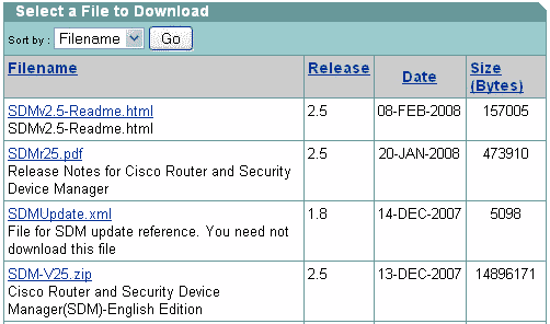
Once you select and download the appropriate zip file (SDM-V25.zip in our example) you'll be able to unzip it and start your installation, however, to ensure your installation succeds, you must telnet into your router or use the console port to log in via CLI, create a username & password, and enable HTTP authentication:
R1# configure terminal
R1(config)# username firewall.cx privilege 15 password ciscorocks R1(config)# ip http authentication local R1(config)# exit R1# copy running-config startup-config Destination filename [startup-config]? (hit enter) Building configuration... [OK] R1#
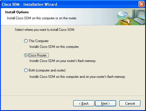
Now start your installation. During the installation you'll be prompted to select if you'd like to install Cisco SDM on your computer, router or both. Select your router:
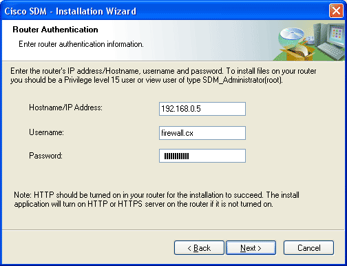
In the next screen, you'll be asked for your router's details (IP Address, username, password) in order to have the SDM software installed on it:
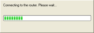
Once you provide all necessary information, you'll get the progress bar indicating the connection towards your router:
Next is the section where you can select a 'Typical' installation or 'Custom'. Select 'Typical' as it will automatically choose the appropriate settings and packages for your router:
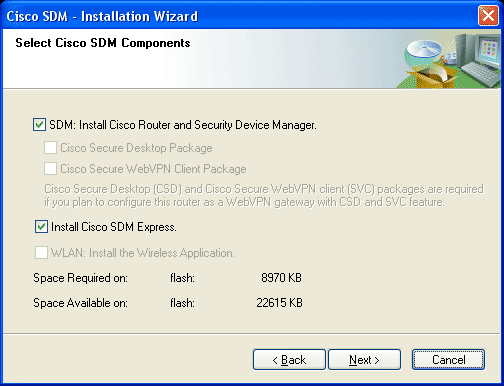
As you can see, SDM v2.5 requires approximately 8.9MB of flash space. Hit 'Next' and your installation begins:
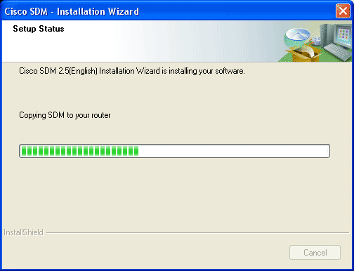
This process will take a couple of minutes as all files are transferred to your router's Flash and final configuration changes are made. Once complete, you'll be given the option to start SDM. If you choose to do so, you'll be redirected to your web browser and asked for the appropriate credentials.
You'll have to make sure you've disabled any pop-up blockers otherwise you won't be able to see the necessary windows that will try to 'pop-up'. After a minute or so you should see the first screen of SDM collecting information on your router:
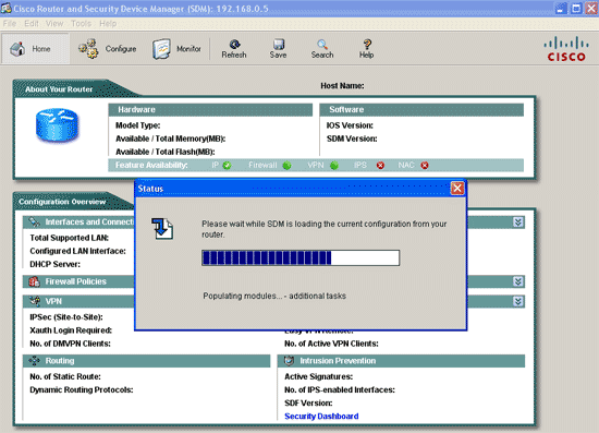
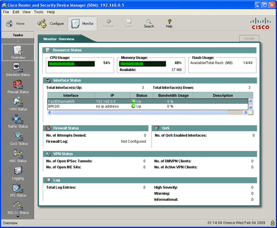
Once this step is over, you'll get your first real-time overview of your router. From here you can configure or monitor any aspect of your Cisco router. The SDM software is constantly being updated with new features, bringing it closer to the flexibility and power of the IOS command line - however, it does still have a long way to go :)
The following screenshot is from the 'Monitor' tab, which can provide a wealth of information regarding the router's status and is extremely useful even for the most experienced:
 |
How To Configure DNS Server On A Cisco Router
How To Configure DNS Server On A Cisco Router
|
Introduction
The DNS protocol is used to resolve FQDN (Fully Qualified Domain Names) to IP addresses around the world. This allows us to successfully find and connect to Internet websites and services no matter where they are. Its usefulness, however, doesn't stop there: local company and private networks also rely on DNS to operate efficiently and correctly.
In many cases, where a local DNS server is not available, we are forced to either use our ISP's DNS servers or some public DNS server, however, this can sometimes prove troublesome. Today, small low-end routers have the ability to integrate DNS functionality, making life easier, but so do Cisco routers - they simply have to be setup and you're done.
This article will show you how to configure your Cisco router to provide DNS services to your network, and make all clients use it as a DNS server. Our easy to follow step-by-step process ensures you'll understand the process and have it running within minutes.
Example Scenario
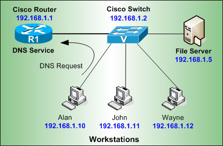
Consider the following network diagram. This is our example network, we'd like to enable the DNS Service so our workstations can properly resolve Internet domains but also local network names.
First step is to enable the DNS service and domain lookup on the router:
R1# configure terminal
R1(config)# ip dns serverR1(config)# ip domain-lookup
Next, we need to configure the router with a public name-server, this will force the router to perform recursive DNS lookups, in other words, for every request it receives from our workstations the router will try to find the answer by asking as many DNS servers it needs, and finally return with an answer:
R1(config)# ip name-server 4.2.2.5
R1(config)# ip name-server 4.2.2.6
The Cisco IOS will allow you to enter up to 6 different name servers (essentially DNS servers). Usually you would use your ISP's DNS server to ensure you have quick responses, then place a few free public DNS servers such as the ones above. This will ensure that you'll get a DNS response from either your ISP or public DNS servers.
Next step is to configure your DNS server with the host names of your local network, this way when Alan's PC trys to ping or connect to Wayne, the router will successfully resolve its netbios name to the appropriate IP address:
R1(config)# ip host alan 192.168.1.10
R1(config)# ip host john 192.168.1.11
R1(config)# ip host wayne 192.168.1.12
R1(config)# ip host john 192.168.1.11
R1(config)# ip host wayne 192.168.1.12
If you now try to ping 'wayne' directly from your router's CLI prompt, you should receive an answer:
R1# ping wayne
Type escape sequence to abort.
Sending 5, 100-byte ICMP Echos to 192.168.1.12, timeout is 2 seconds:
!!!!!
Success rate is 100 percent (5/5), round-trip min/avg/max = 1/1/4 ms
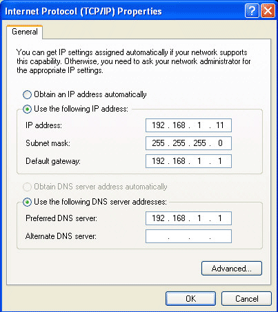
At this point, you can configure your workstations to use your router's IP address as the primary DNS server:
Cisco Router Password Recovery
Cisco Router Password Recovery
|
Introduction
Password recovery is a fairly frequently used procedure for administrators and engineers. Even though we usually stack our passwords in some word, excel or text file, it's very easy to forget to update them when changes occur. The end result is you find yourself locked out of the device, wondering what on earth could be the password.
Accessing a Cisco router requires certain privileges. Depending on the router's configuration, you might be required to firstly log into the router and then enter the popular 'enable' password to elevate your access to privileged mode, from where you can issue configuration commands.
This article will show you how you can gain full administrator access to a Cisco router, bypassing all security passwords. The password recovery process, however, can be rendered useless if the administrator has previously configured the router not to allow this process to take place. In this case, the router will warn the user and, if he proceeds, all configuration will be erased, so there will be nothing to recover!
Example Scenario
Consider we have a Cisco router (2610 for our example - this procedure is the same for all routers) and we are unable to access it due to a lost password. Console and VTY (telnet) sessions ask for a password which we do not have:
R1 con0 is now available
Press RETURN to get started. User Access Verification Password: ***** Password: ******** Password: *** % Bad passwords
Even if we were able to successfully log into the router, but couldn't provide the router with the correct 'enable' password, we would still need to perform a password recovery procedure.
To initiate the password recovery procedure, connect the rollover cable to the console port, then power the router off and back on. As soon as you receive a prompt showing the boot process, hit Ctrl-Break:
System Bootstrap, Version 11.3(2)XA4, RELEASE SOFTWARE (fc1)
Copyright (c) 1999 by cisco Systems, Inc. TAC:Home:SW:IOS:Specials for info PC = 0xfff0a530, Vector = 0x500, SP = 0x680127c8 C2600 platform with 65536 Kbytes of main memory program load complete, entry point: 0x80008000, size: 0xf54134 PC = 0xfff0a530, Vector = 0x500, SP = 0x83fffe68 <ctrl + Break> monitor: command "boot" aborted due to user interrupt rommon 1 >
You'll immediately see the 'rommon' prompt, indicating we are in 'rom monitor' mode. This is a mini-IOS that allows you to perform very specific tasks in order to recover your router.
Now, to skip our password-protected configuration, we instruct the router to by-pass the configuration located in NVRAM during bootup, and reset the router:
rommon 1 > confreg 0x2142
You must reset or power cycle for new config to take effect rommon 2 > reset The router will now reset and start its normal bootup process, however, the current configuration will be ignored. When the bootup is complete, you will be prompted to 'enter the initial configuration dialog', answer 'no':
System Bootstrap, Version 11.3(2)XA4, RELEASE SOFTWARE (fc1)
Copyright (c) 1999 by cisco Systems, Inc. TAC:Home:SW:IOS:Specials for info C2600 platform with 65536 Kbytes of main memory program load complete, entry point: 0x80008000, size: 0xf54134 Self decompressing the image : ## <output omitted> --- System Configuration Dialog --- Would you like to enter the initial configuration dialog? [yes/no]: no Press RETURN to get started! Next step is to enter 'Privileged Mode' and load the router's configuration from nvram. Then reset the 'enable' or 'secret' password. To be sure, we're showing how to reset both, but we'll only need to use the 'secret' password. In addition, we are going to reset the console port's password:
Router>
Router> enable Router# copy startup-config running-config Destination filename [startup-config]? (hit enter) Building configuration... [OK] Router# configure terminal Router(config)# enable password cisco Router(config)# enable secret enter Router(config)# line console 0 Router(config-line)# password hello Router(config)# username admin privilege 15 secret enternow
If you use the 'login local' command you'll need to reset the user account of the password you have lost (in our example, it's 'admin').
Lastly, we need to change the 'configuration register' so the router will load the newly modified configuration next time it reboots, save our settings and reboot the router:
Router(config)# config-register 0x2102
Router(config)# exit Router# copy running-config startup-config Destination filename [startup-config]? (hit enter) Building configuration... [OK] Router# reload
The router will now reload and use the new configuration that contains the newly set passwords.
When the router reboots, log in and check your configuration. If you find any interfaces in the 'shutdown' state, you'll need to use the 'no shutdown' command to bring them back up.
Again, don't forget to save your configuration once all changes are complete!
|
Subscribe to:
Posts
(
Atom
)

